
ESEC
This web application conducts analysis of a strip with 1 m width under pure moment.
It can be used for following applications:
1. Design of 1 m strip in RC Flat Slab or Solid Slab under pure moment.
2. Design of 1 m strip in RC Raft under pure moment.
3. Design of 1 m strip in RC Wall under pure moment.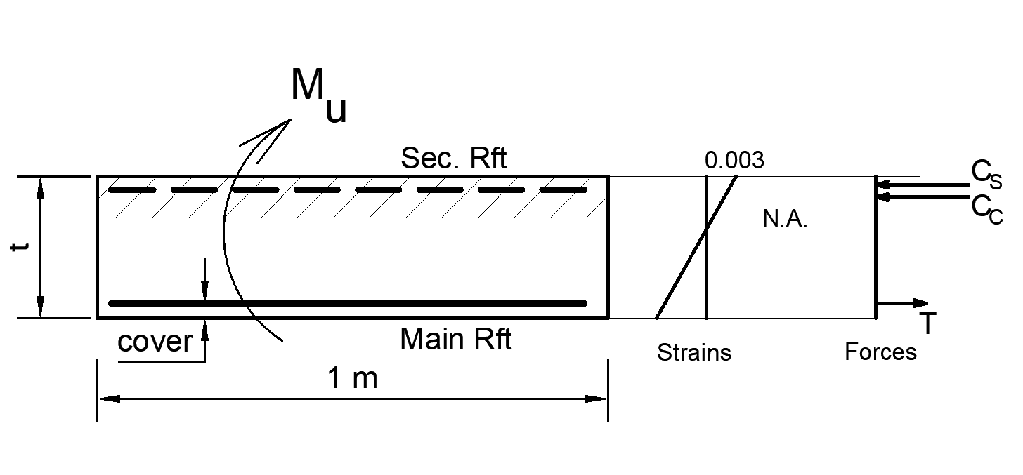
1. Design of 1 m strip in RC Flat Slab or Solid Slab under pure moment.
2. Design of 1 m strip in RC Raft under pure moment.
3. Design of 1 m strip in RC Wall under pure moment.
This web application conducts check on punching for Flat slab or Post-tensioned slab with/out shear reinforcement. The punching check is conducted using the following approaches:
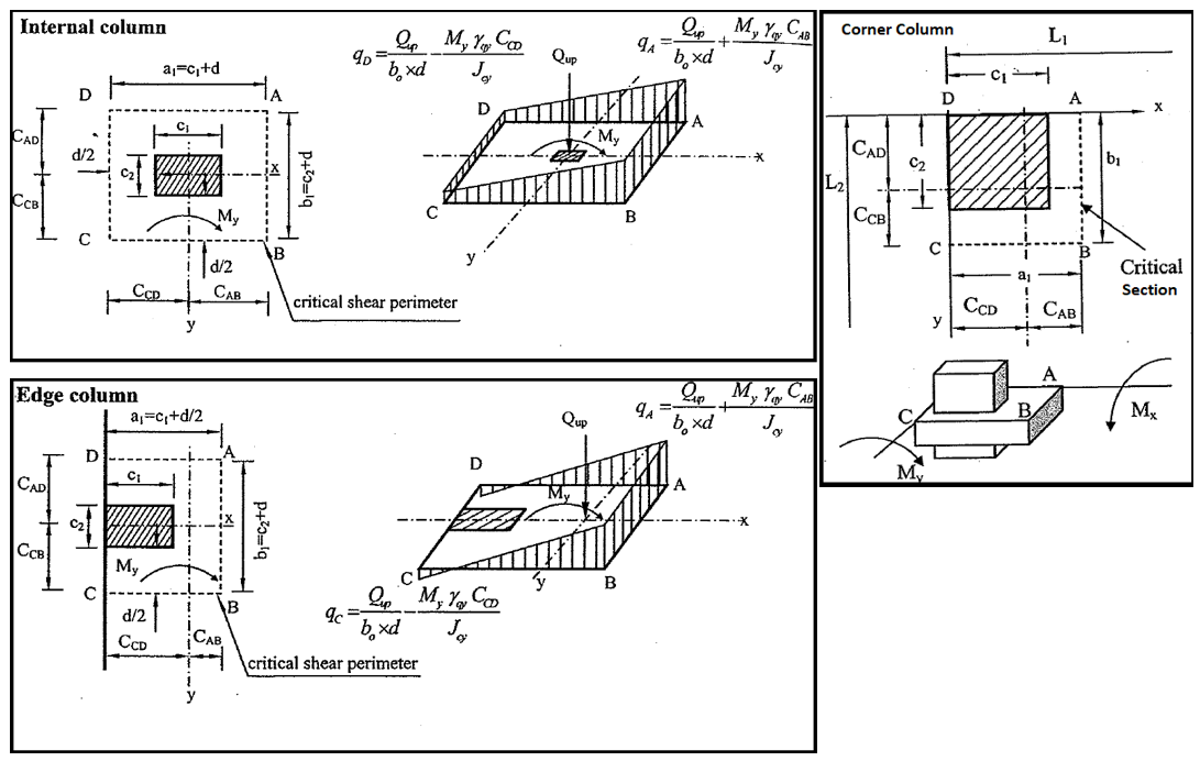
Approach 1:
Using Simplified Method at Section at d/2 and Simplified Method at Outside Stirrups Section
* In Simplified Method, a β-factor is used instead of considering the applied moment at the punching critical section.
Approach 2:
Using Detailed Method at Section at d/2 and Simplified Method at Outside Stirrups Section
* In Detailed Method, Punching stresses are estimated considering the applied moment at the punching critical section in addition to the axial load, without including β-factor.
This web application conducts analysis of a RC beam section twice:
1. Under pure moment (ignoring applied shear force and axial load)
2. Under shear force and axial load (ignoring applied moment)
1. Under pure moment (ignoring applied shear force and axial load)
2. Under shear force and axial load (ignoring applied moment)
This web application conducts analysis of two sections in RC beam under pure moment:
Section 1 is subjected to +ve moment: Bottom bars are main Rft while stirrup hangers are secondary Rft.
Section 2 is subjected to -ve moment: Top bars are main Rft while bottom bars are secondary Rft.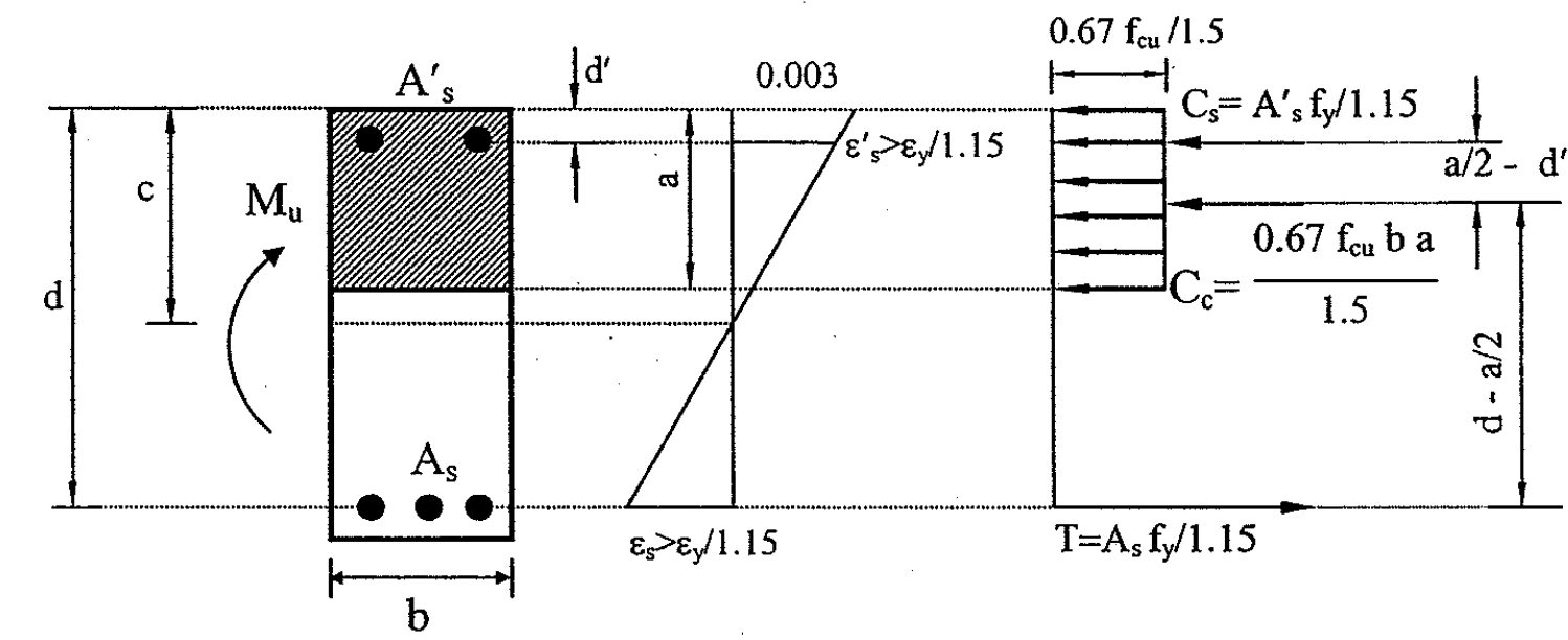
Section 1 is subjected to +ve moment: Bottom bars are main Rft while stirrup hangers are secondary Rft.
Section 2 is subjected to -ve moment: Top bars are main Rft while bottom bars are secondary Rft.
This web application conducts analysis of the critical section of in RC beam under shear.

This web application conducts design of a RC beam section twice:
1. Under pure moment (ignoring applied shear force and axial load)
2. Under shear force and axial load (ignoring applied moment)
1. Under pure moment (ignoring applied shear force and axial load)
2. Under shear force and axial load (ignoring applied moment)
This web application conducts design of a RC beam section under pure moment.

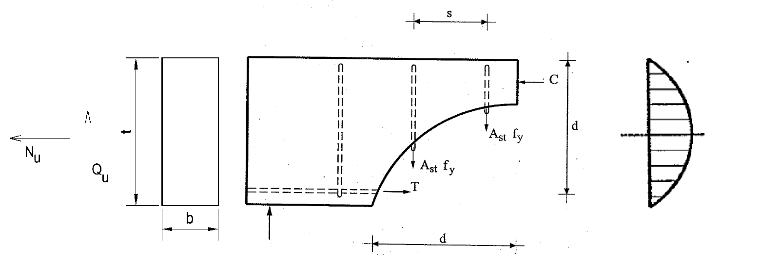
This web application conducts design of a RC beam section under shear force and axial load.
This web application evaluates the safety of a RC column under axial load and biaxial moments. It offers two options:
1. Single Case Evaluation: Assesses safety under one set of loading conditions (Pu, Mux, Muy).
2. Multiple Case Evaluation: Assesses safety under multiple sets of loading conditions (Pu, Mux, Muy).
Safety is evaluated using the following methods:
1. Capacity/Demand (C/D) Ratio:Similar to the spColumn software. A 3D interaction diagram is plotted, and the nearest point to the applied loading (ΦPu, ΦMux, ΦMuy) on the diagram is identified. Cases are considered safe if the C/D ratio is greater than 1.0.
2. Capacity/Demand (C/D) Ratio Using ECP 203-2020 Simplified Method: Employs the simplified method from ECP 203-2020. Cases are deemed safe if the C/D ratio is greater than 1.0.
3. Demand/Capacity (D/C) Ratio: Similar to ETABS software. A 3D interaction diagram is plotted and used to find the nearest point to the applied loading (ΦPu, ΦMux, ΦMuy). Cases are considered safe if the D/C ratio is less than 1.0.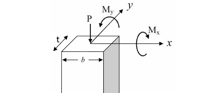
This web application analyzes RC Eccentric Section under one Moment and Axial load. It is used for:
* Analysis of 1 m strip in RC Flat Slab, Solid Slab, Raft, or Wall
* Analysis of RC beam with any width.
* Straining actions: Pure Moment, Pure Axial load, or Moment & Axial load.
* Cracking check: Simplified method or Crack width method.
* Crack width calculations are conducted twice: 1. Using Rft from Cracked Section Analysis 2. Using user-defined Rft.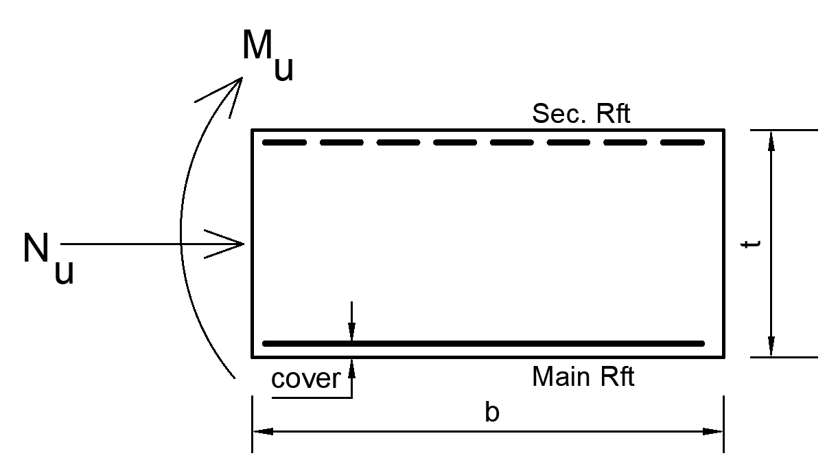
This web application calculates and plots horizontal and vertical response spectrum. It also estimates the base forces for a certain building defined by (weight, height, connection type, period, importance, seismic system, and response modification factor).
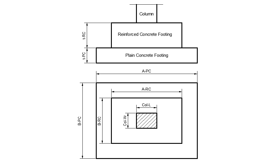
This web application calculates the capacity of an RC isolated footing by determining the minimum load needed for safety against RC moment, soil pressure, punching, one-way shear, and PC moment.
This web application has the following features:
1. allow for the import and display of ETABS models in 3D view.
2. design beams, columns, and footings under various load cases, including axial load and biaxial bending moment.
3. support multiple international codes, such as American ACI 318, British BS8110, and Egyptian ECP 203.
4. shows demand/capacity (D/C) ratios for columns for the following 5 approaches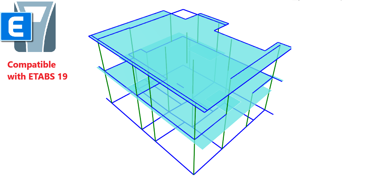
Approach 1: D/C ratios are calculated by ETABS software.
Approach 2: Madd is calculated using design code in ETABS and 3D-interaction diagrams are calculated by design code in ESEC.
Approach 3: Madd is calculated using ECP code (k=1.3) in ESEC and simplified ECP method (Item 6-4-6-2-1) is used (2D-interaction diagrams) by magnifying one moment and neglecting the other moment.
Approach 4: Madd is calculated using ECP code (k=1.3) in ESEC and simplified ECP method (Item 6-4-6-2-3) is used (2D-interaction diagrams) by magnifying both moments and taking larger D/C ratio.
Approach 5: Madd is calculated using ECP code (k=1.3) in ESEC and 3D-interaction diagrams are calculated using design code in ESEC.
5. calculate (D/C) ratios for beams and isolated footings.
Approach 2: Madd is calculated using design code in ETABS and 3D-interaction diagrams are calculated by design code in ESEC.
Approach 3: Madd is calculated using ECP code (k=1.3) in ESEC and simplified ECP method (Item 6-4-6-2-1) is used (2D-interaction diagrams) by magnifying one moment and neglecting the other moment.
Approach 4: Madd is calculated using ECP code (k=1.3) in ESEC and simplified ECP method (Item 6-4-6-2-3) is used (2D-interaction diagrams) by magnifying both moments and taking larger D/C ratio.
Approach 5: Madd is calculated using ECP code (k=1.3) in ESEC and 3D-interaction diagrams are calculated using design code in ESEC.
This web application is developed by: Assoc. Prof. Ahmed Elansary, Faculty of Engineering, Cairo University
*ResearchGate
Check out the desktop version of the software
Any iquiries or suggestions for improvements should be submitted to:
aelansa2@uwo.ca
.